COMSOL Tutorial for MEMS Sensor Topology Optimization: A Step-by-Step Guide
Explore our detailed COMSOL tutorial on MEMS sensor topology optimization. Learn how to enhance nanomechanical sensors’ performance in our step-by-step guide.
Introduction
In the dynamic realm of nanotechnology, microelectromechanical systems (MEMS) nanomechanical sensors have become essential tools for detecting chemicals and biomolecules with unparalleled sensitivity and specificity. Piezoresistive readout-based nanomechanical sensors, in particular, are notable for their ability to function in opaque liquid environments and eliminate the need for laser alignment, thereby facilitating in situ detection of various biomolecules. However, they face challenges such as low signal-to-noise ratios and sensitivity limitations, necessitating innovative solutions and optimizations.
This tutorial provides a detailed guide on setting up a COMSOL model for topology optimization, aiming to enhance the surface stress sensing performance of a piezoresistive nanomechanical sensor. For an introduction to this optimization problem, refer to this recent blog post.
Setting Up the Model
Geometry Definition
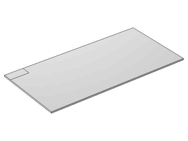
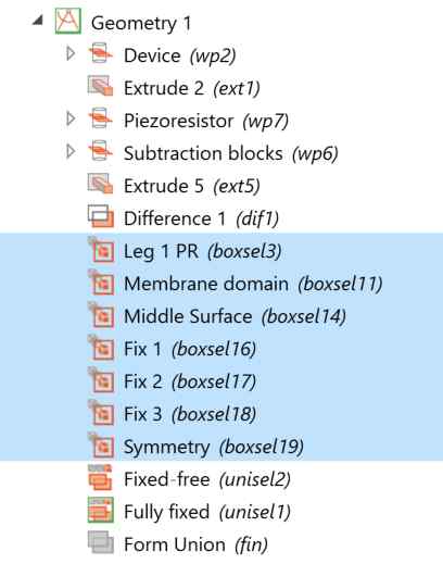
The whole geometry consists of a large rectangular block representing the sensor structure, with the piezoresistor depicted as a small patch on the upper surface. To reduce computational load, only half of the geometry is modeled, as illustrated below.
Box selection is employed for consistent boundary conditions as the topology evolves, a technique also used in this COMSOL tutorial.
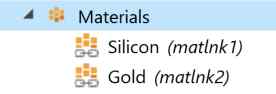
Materials
Silicon is assigned to the large rectangular block, while the immobilization layer, which can be polymer or gold, is assigned to the upper surface of the block. The materials assignment is done by links as the same materials are referenced twice in the two components in this model file.
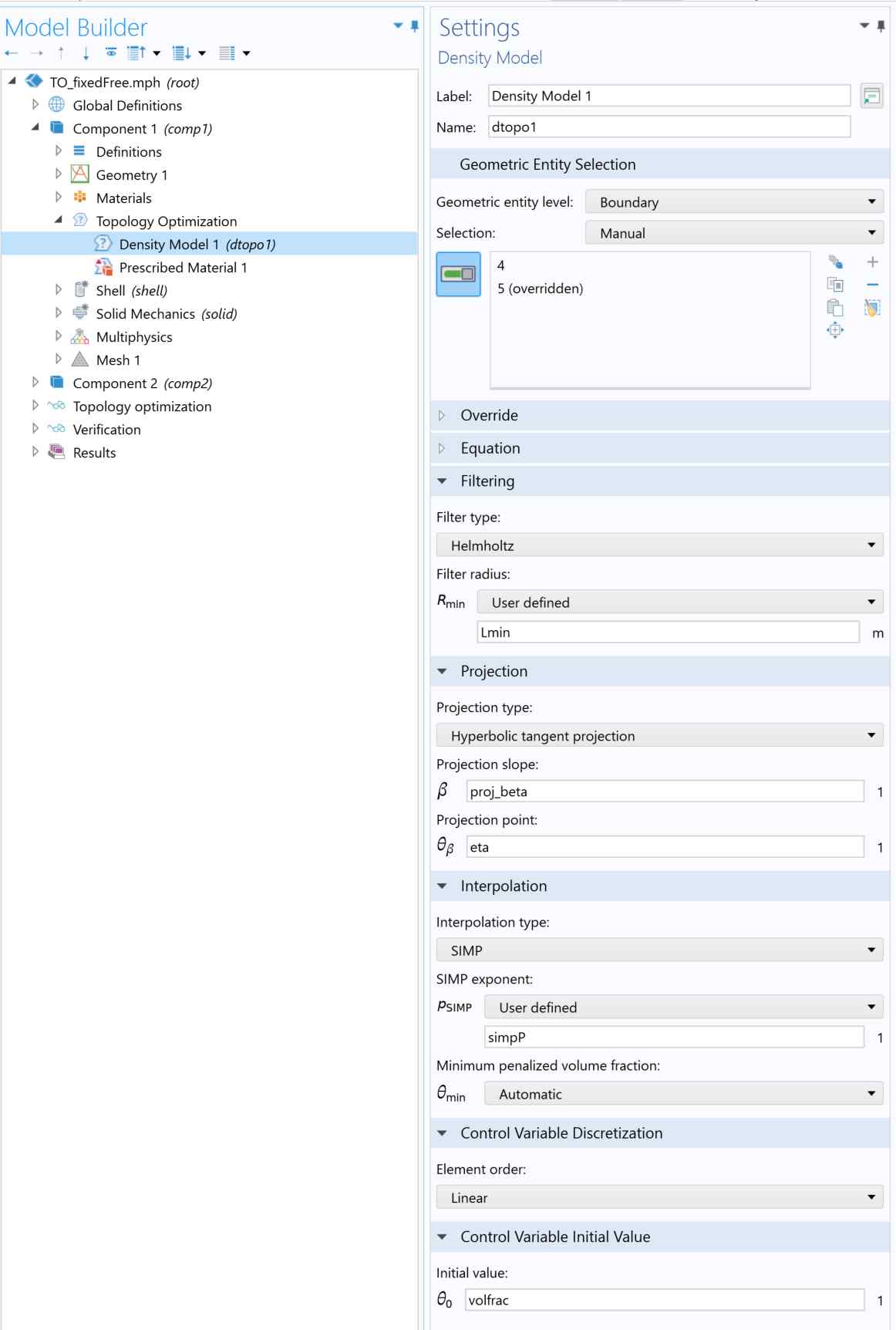
Topology Optimization
A detailed discussion of the optimization parameters can be found in a previous post, but in summary:
- Filter Radius: Defines the smallest design feature and is set as 1.2 times the mesh size. This parameter can be used for parameter continuation, as seen in this example.
- Projection Slope & Point: These parameters in the Heaviside function are used for parameter continuation (example) and robust formulation.
- Interpolation Type: SIMP is typically sufficient, but RAMP may be considered for dynamic problems.
- SIMP Component: Usually set to 3, but can be adjusted for parameter continuation, as demonstrated in this example.
- Volume Fraction: Determines the initial amount of material in the design domain. This value is often problem-dependent, typically set to 0.5, 0.6, or without limitations.
- Prescribed Material: The density of the piezoresistor region is set to 1, ensuring its presence throughout the optimization process.
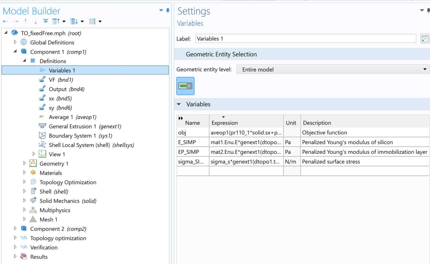
Physics
-
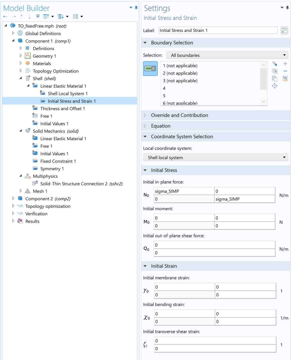
Shell Interface:
- Initial Stress & Strain: Surface stress is implemented here. The stress is defined in the “Variables” section as a product of set surface stress and element density, the optimization variable during topology optimization. This setting implies that the presence of stress requires the presence of the element. The general extrusion function (genext()) is used to map the material density at the 2D design domain onto the shell and solid interface. The same dependence on element density holds for material stiffness as well.
- Thickness & Offset: Define the thickness of the immobilization layer.
-
Solid Mechanics Interface:
- Linear Elastic Material: Define an explicit elastic matrix instead of using predefined material properties via Young’s modulus and Poisson’s ratio. This approach will be useful later when modifying material anisotropy.
- Fixed Constraint: Implement the fixed-free boundary condition.
- Symmetry: Account for the other half of the design.
- Discretization Scheme: Use first-order (linear) elements for both shell and solid mechanics to reduce computational load.
- Multiphysics coupling: The shell and solid mechanics interfaces are coupled through the “Solid-Thin Structure Connection” in the “Multiphysics” node.
Meshing
A swept method with quad mesh is used to sweep through the thickness direction. Typically, three meshes along the thickness direction are sufficient. The parameter “meshsz” controls the mesh size; smaller sizes give a more detailed design but with an increase in computational cost.
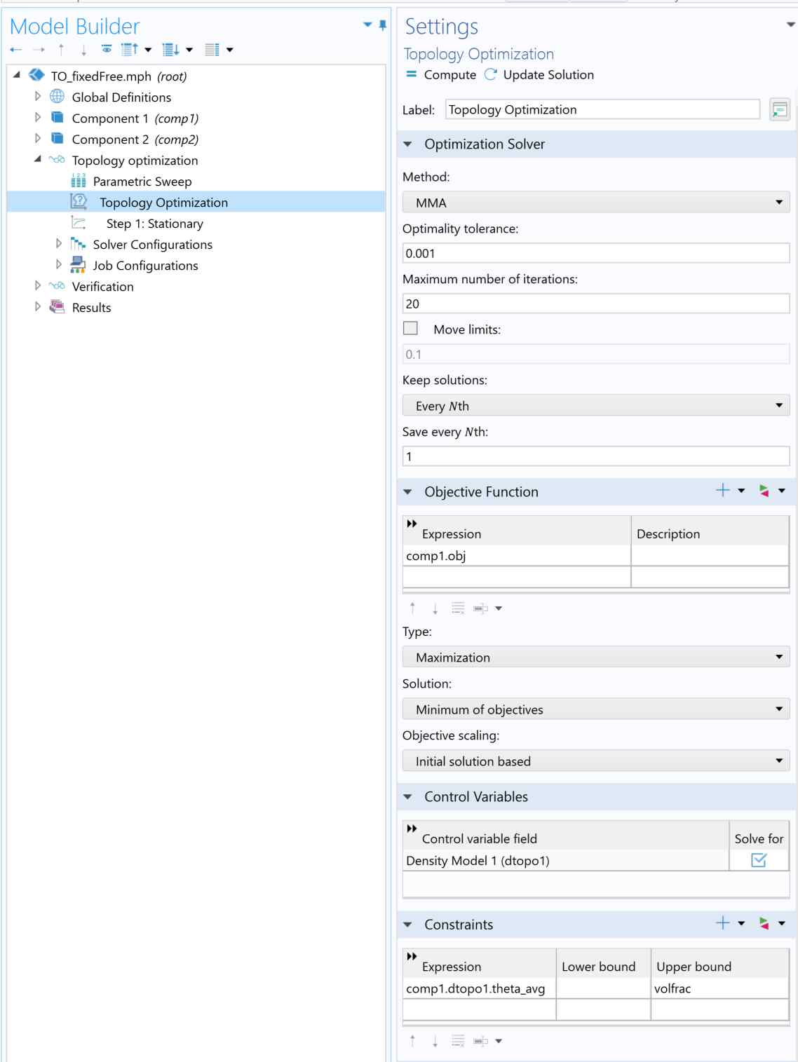
Study - Topology Optimization
- Parametric Sweep: This is utilized for parameter continuation. Adjusting \(\beta\) will influence the blurriness of the design boundaries. A low \(\beta\) will lead to a blurry boundary, and vice versa. Ramping \(\beta\) from low to high helps to ensure global optimality. Similarly, \(r_{min}\) and \(p\) can also be added in this section as continuation parameters, but they are omitted here for simplicity.
- Design Objective: This is set to the output of the piezoresistor, as defined in the “Variable” section.
- Optimization Type: Depending on the sensor’s bending direction, this can be set to either “maximization” or “minimization”.
- Solution: For a robust formulation, this is set to “minimum of objectives,” aiming to improve the worst design among the three. If the optimization type is set to “minimization”, then this section should be set to “maximum of objectives,” making it opposite to the optimization type.
- Constraints: The volume fraction constraint is implemented as the upper bound, constraining the maximum amount of materials being used in the design.
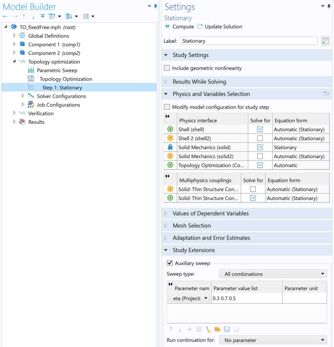
Solver Settings
In the first study, we solve only for shell, solid mechanics, and topology optimization in Component 1. In the auxiliary sweep, a sweep of \(\eta\) for robust formulation is implemented. This ensures that the worst-performing design is improved upon and is associated with the “Solution” section in the topology optimization study settings. To disable robust formulation, simply uncheck the auxiliary sweep.
Post-Optimization Steps
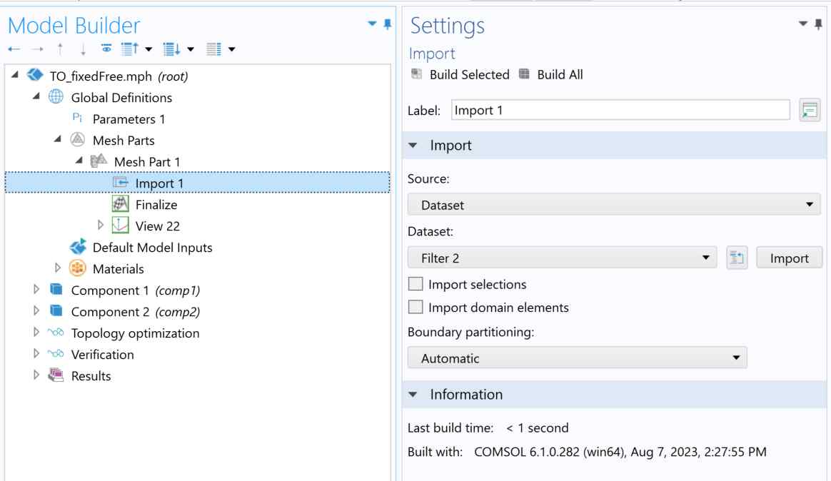
After the optimization, one clicks the import button in the Mesh part node in the global definitions section to import the results into a second study for verification.
To construct the verification study, component 2 is built with the optimized geometry while all physics remaining the same. The only difference is the element order, which is changed from first-order (linear) to second-order (quadratic) for accurate FEA evaluation. The verification study node associated with this component calculates the exact performance and stress profile of the optimized design.
Optimization Results
Using the Material Distribution graph, the history of optimization as a function of the iteration number can be observed and animated using the animation functionality in COMSOL. Note that only the optimization history comes directly from the first study; the detailed analysis of the structure and their accurate performance are all obtained from the second verification study.
All other results have been presented in a recent blog post, so please refer to there for more details.
Further extension
Once the optimization model is operational, it can be easily scaled up for an extensive sweep over various geometry parameters. This facilitates an in-depth investigation into how the optimized design depends on initial geometrical constraints. For batch calculations through MATLAB-Livelink, see the script here. A use case of this workflow can be found in this paper.
Further, this model can be modified to investigate optimized designs with alternative boundary conditions, bending modes, integrated readout, and alternative materials, providing an easy way to investigate optimal designs under various applications and materials constraints.
To wrap up
This tutorial offers a comprehensive workflow for topology optimization in COMSOL. Ensure you follow each step carefully and adjust parameters as needed based on your specific requirements.
Since this workflow requires reimporting the optimized design into a second study within the same model file (similar to a COMSOL tutorial), generating a compact .m file is currently not supported by COMSOL. If you’re interested in accessing the .mph file, please feel free to contact either me or my supervisor.
Funding: This work is funded by the National Institute for Materials Science (NIMS) and the University of Tsukuba, Japan.