Beneath the Surface: Understanding Wrinkle Formation
Introduction
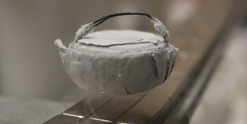
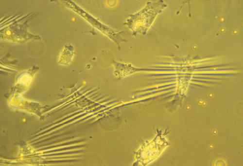
From the tiny cells that make up the skin on our bodies to the complex geological formations on Earth, wrinkles are a ubiquitous and fascinating aspect of our world. They’re not just aesthetically intriguing—they are a key to unlocking various innovations in fields as diverse as healthcare, consumer electronics, and marine engineering. In this blog post, we’ll dive into the mechanics of wrinkle formation and demonstrate its relevance to the industry, all backed up by a computational model developed using COMSOL Multiphysics. If you’re an enthusiast of how tiny mechanical behaviors can lead to industry-changing technologies, you’re in the right place.
This topic is also related to our earlier contribution in a paper here.
The Physics of Wrinkles: Stretched or Compressed Sheets
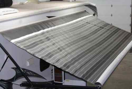
Wrinkles can form when thin sheets are either stretched or compressed, such as when the paper is pulled taut or curtains sag due to gravity. The periodic direction of these wrinkles is dictated by a complex balance between two forces: strain energy and bending energy. This tug-of-war between stretching and compressing creates wrinkles at an intermediate wavelength, leading to the wrinkle formation we observe.
The Bilayer Model
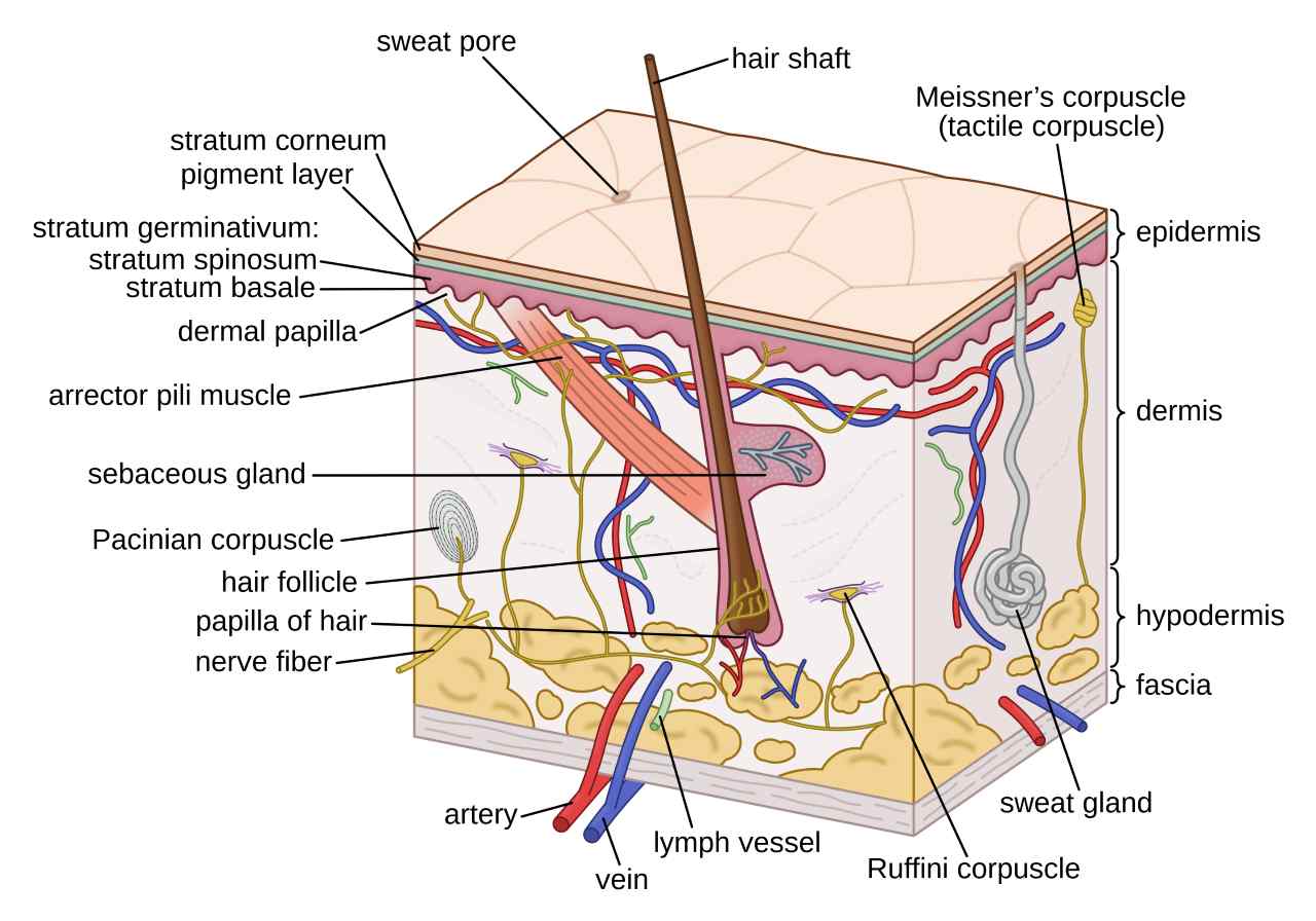
When it comes to more complex systems like human skin, a bilayer model becomes necessary. In this model, a stiff, thin layer (epidermis) is bonded to a soft, thicker layer (dermis). Under compression, wrinkles form, driven by the energetic interplay between these layers.
Simulating Wrinkles: A COMSOL Walkthrough
To fully grasp the wrinkle formation mechanism, theoretically, we can turn to elastic foundation formulations, Fourier analysis, and dimensional analysis. By applying these theories, we can predict parameters like wrinkle wavelength and critical strain, valuable for applications like precision engineering and wearable technology. An example of these derivations can be found in literature for an in-depth explanation.
To bring these theories to life, we use COMSOL Multiphysics to simulate the bilayer system. This simulation provides a practical tool for engineers to predict how different materials will behave under stress.
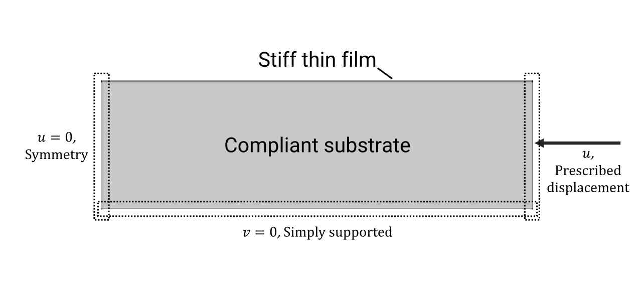
Geometry and Boundary Conditions
The bilayer can be modeled by 2D rectangular plate elements, with dimensions chosen to represent commonly studied experimental systems of Polydimethylsiloxane (PDMS) substrate and the oxidized stiff layer of silicate discussed in here and here. An initial imperfection is introduced to trigger the onset of instability, and the amplitude of the imperfection determines the abruptness of the instability, as discussed in this work. The imperfection is introduced to the thin film layer through a sinusoidal parametric curve in the geometry definition.
The left boundary of the bilayer is set to symmetry, preventing motion along the x-axis, while the right boundary is set to have a described displacement along the x-axis, which is used for applying the compressive strain. The top boundary is free, and the bottom boundary is constrained in the y direction and it can only move along the x-axis.
Materials
The soft substrate is modeled to have a stiffness of 1 MPa, which is the typical Young’s modulus of PDMS, while the thin film has a stiffness of “Sr * 1 MPa”, where the Sr means the stiffness ratio between the thin film and the substrate, and it is set to be 100 here according to here and here.


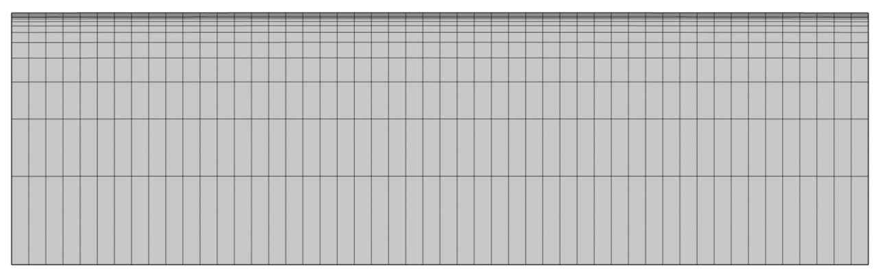
Meshing the Model
The thin film is meshed with quadratic quadrilateral mesh using the mapped node with 50 and 3 meshes along the length and thickness directions, respectively, and a mesh convergence study confirms the adequacy of the chosen mesh density.
The substrate is meshed with a dense mesh close to the thin film, and the density decays exponentially toward the bottom edge. The dense mesh near the top surface ensures a sufficient resolution to resolve the stress distribution near high curvature regions.
Post-processing and Analysis
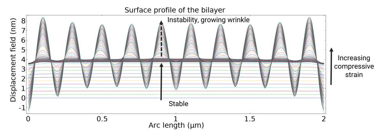
The wrinkle formation under increasing compressive load is animated below. The increasing compressive strain is implemented by a parametric sweep with continuation on the last parameter.

As the bilayer is getting squeezed, the surface first moves uniformly along the y direction. When the compression approaches the critical strain, wrinkles emerge, and the amplitude of the wrinkle grows with increasing compressive strain. The wrinkle period is around 0.2 um, which agrees accurately with theoretical estimation.
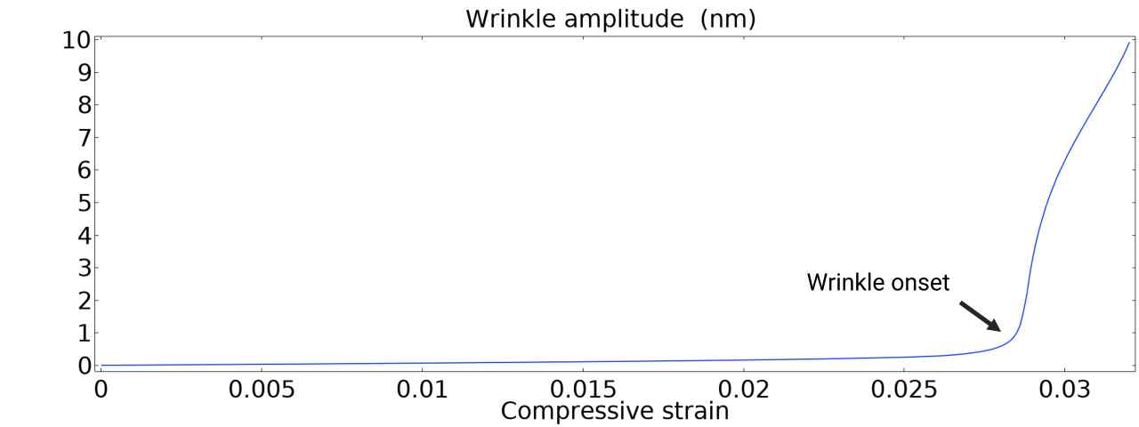
By plotting the amplitude of wrinkle as a function of compressive strain, one obtained the following figure that clearly indicates the onset of instability. According to the formula presented in the theory section, the critical strain is estimated to be 2.4%, agreeing reasonably well with the simulation.
Higher-order Modes
If the compressive strain increases further, the sinusoidal wrinkles will undergo periodic doubling and evolve to higher-order instability modes, such as crease and fold, depending on the stiffness and thickness of the bilayer. The phase diagram of different modes has been calculated and verified by numerical and experimental studies.
However, higher-order modes are beyond the capability of the current model due to the poor convergence properties of the simple parametric sweep that is used to implement the increasing compressive strain. To investigate these highly nonlinear phenomena, methods like displacement control, as presented in this blog post, are required for better convergence performance.
Conclusions and Next Steps
This basic model serves as a starting point for more complex simulations, such as wrinkles induced by swelling. When extending the 2D model to 3D, one may need to replace the plate element used here with a coupled sell-solid mechanics interface, see here for an example. Although 3D simulations would require more time to compute, they could provide insights into wrinkles on curved surfaces and complex wrinkle patterns.
The COMSOL .m and .mph files for this model are available on this repo, please feel free to use it as a basis for your own simulations.
Funding: This work is funded by the National Institute for Materials Science (NIMS) and the University of Tsukuba, Japan.